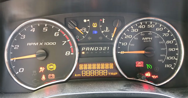
Warnings that an ABS light is blinking often indicate that there is a problem. You could get a “false” code on your dashboard if the anti-lock braking system (ABS) does not detect a genuine issue during its own self-diagnosis but you are certain that there is no issue with your vehicle. In either case, you will need to examine the source code in order to determine what the issue is.
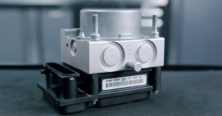
Depending on the circumstances, extracting error codes from an ABS system might be a simple or challenging process. Early Bosch 2 import ABS systems do not have a provision for code storage. In the event that the light is on, you will need to do targeted circuit testing in order to locate the source of the problem.
Newer ABS system codes
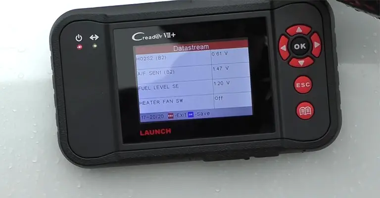
Because many modern ABS systems do not contain flash codes, you will need to employ a scanning device in order to get the system’s information. All Bendix systems are included in this category.
The majority of modern ABS systems also further provide advanced diagnostic tests, such as the capability to store snapshot data affiliated with an accident code, code background, and the capability to take two-way feeds from a scan tool to exert different components in the ABS system, such as the solenoid valves, ABS warning lamp circuit, and so on.
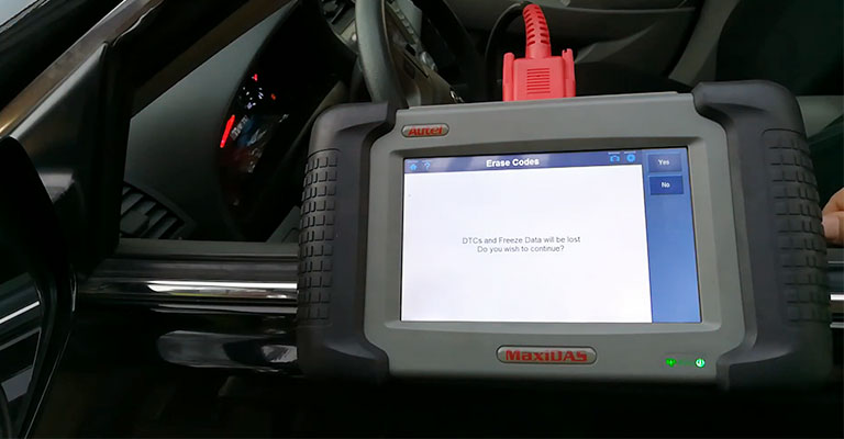
A more advanced kind of scan tool or a specific ABS tester that enables a bidirectional (two-way) connection between the ABS module and the scan tool is required in order to evaluate these kinds of systems. This gives you the opportunity to verify the performance of the different components and solenoids, as well as to exercise the various solenoids, which is a method that is often required to bleed the brakes on these cars.
Even while all that is required to read and clear fault codes on the majority of ABS systems is a scan tool, the fault codes themselves are not enough to solve the issue. A code is nothing more than information that the system has self-diagnosed a problem with one of its components or circuits.
It does not instruct you on what should be substituted. In order to solve the issue, you will need to consult the detailed diagnostic procedures outlined in a service manual and use a method of elimination to zero in on the source of the problem. If you jump to conclusions, you run the risk of making an incorrect assumption.
What is more, intermittent problems may not set a fault code. So if there is no code, do not assume everything is fine. You have to check the operation of the system as well as individual components to figure out what is wrong.
ABS Blink Code Diagnostics
Any kind of electrical problem with the trailer ABS may be found and fixed with the Meritor WABCO Enhanced Easy-Stop Trailer ABS ECU. A code has been assigned to each of the issues. The electronic control unit (ECU) will save the fault code in the storage if it detects a problem. Active and stored faults are the two categories that defects fall into.
Active faults are ones that are presently present in the system and include things like a wire that is damaged. Faults that have happened in the past but do not now exist are referred to as stored faults. After the repairs have been finished, active faults may be erased from the system.
The TOOLBOX Software or the Pro-Link 9000 are the only tools that can be used to diagnose stored errors.
When there is a problem, the electronic control unit (ECU) will let you know by turning on both the internal and exterior indication bulbs. Typically, the exterior ABS indication bulb will be installed on the left side of the trailer’s rear, close to where the wheels are located.
How to obtain ABS Blink Codes
There are two different approaches of get blink codes:
- Power Activation for the Ignition (recommended method)
- Diagnostic Tool
Even while the ECU’s memory may hold a number of different faults at once, it can only show a single blink code at a time. Because of this, it is essential to do a second check of the blink codes after any problem has been fixed.
After you have fixed the first problem, any further fault codes that were stored in the memory will not flash until you fix the original problem. The TOOLBOX Software and the Pro-Link 9000 both have the ability to perform end-of-line test modes, as well as remove any defects that have been stored.
How To Obtain Abs Blink Codes Using Ignition Power Activation
This process works on trailers. Ignition Power Activation is the process of using the vehicle’s ignition switch or interjecting the electricity on the blue wire in a different way in order to show blink codes on the trailer ABS indicator lamp that is situated on the edge of the trailer.
This can be done by employing the Ignition Power Activation button on the trailer’s control panel. This strategy can only be used with vehicles that have consistent power. In order to get blink codes by activating the ignition power, the following operation must be carried out:
- Hold the ignition switch on for no more than five seconds after turning it on. The warning light for the ABS system will be illuminated.
- Ensure the ignition switch is in the “off” position. The indication bulb for the ABS will eventually turn off.
- To start the engine, turn the ignition switch on. The indication bulb for the ABS will then turn on briefly before turning off again.
- The trailer’s ABS indicator bulb will flash the blink code three times before moving on to the next message.
ABS Blink Codes
These codes, in general, apply to trailers that were sold on the market in the United States after March of 2001.
Light | Blink code | Cause | location | Checks |
3 | Sensor BU1 | Sensor or sensor cable. Follow the cable from the port labeled with port number (YE1, BU1, …) to the wheel end. | Check the wiring to see if there is a short or no circuit, the hub to see if it has an excessive runout, the exciter ring to see if it is damaged, and the sensor gap. | |
4 | Sensor YE1 | |||
5 | Sensor BU2 | |||
6 | Sensor YE2 | |||
7 | External Modulator | External modulator and/or cable | Make sure there is a connection and that the cable is continuous. Check the operation of the valve. | |
9 | Internal Modulator | Internal Inlet Control #2 | Verify the proper installation. If the code continues, contact the manufacturer. | |
10 | Internal Inlet Control #1 | |||
11 | Internal Outlet Control | |||
14 | Power Supply | Power cabling and connectors | Check that the electrical installation was done correctly. Verify the power supply. | |
15 | ECU Failure | ECU Internal Failure | Verify the appropriate installation. In the event that the code persists, | |
16 | SAE J1708 Failure | Get help from the manufacturer. | ||
17 | SAE J2497 Failure | |||
18 | Generic IO Failure | Cabling | Check that the electrical installation was done correctly. Verify the power supply. |
Leave a Reply